

1. Introduction to Modulation and Demodulation
1.1 Baseband and Carrier Communication
Modulation is a fundamental concept in communication systems that involves altering a carrier signal's properties to encode information. Baseband communication transmits data directly on the signal's frequency, while carrier communication employs a carrier wave to carry information.
o Baseband communication
In baseband communication, message signals are transmitted in their original form without any alterations. However, this direct transmission approach faces limitations when dealing with signals like audio and video, which typically contain substantial low-frequency components. These signals are not suitable for efficient wireless transmission over radio links. Instead, for long-distance communication, dedicated user channels are allocated, often employing mediums such as twisted pairs of copper wires or coaxial cables.
Baseband signals inherently possess overlapping frequency bands, and if multiple signals share a common channel, they will inevitably interfere with one another. To address this issue, a technique called modulation is employed. Modulation involves the alteration of multiple baseband signals by shifting their spectra to non-overlapping frequency bands. This facilitates the sharing of a single physical channel by multiple users and makes effective use of the broader available channel bandwidth. This method is known as frequency division multiplexing (FDM).
For long-range communication over radio links, modulation is also essential. It serves to shift the signal spectrum to higher frequencies. This shift enables the efficient radiation of power by antennas with reasonable dimensions, a crucial aspect of long-haul wireless communication. Additionally, modulation is employed to trade transmission bandwidth for improved performance in the presence of interference. This technique helps optimize the use of available resources and ensures reliable communication in various scenarios.
o Carrier communication
Carrier communication is a method that employs modulation to manipulate the frequency spectrum of a signal. When it comes to analog modulation, one of the fundamental characteristics (be it amplitude, frequency, or phase) of a sinusoidal carrier signal with a high frequency, denoted as fc in Hertz or ωc at 2πfc in radians per second, undergoes a linear alteration in response to the baseband signal m(t). This modulation process gives rise to various forms of modulation, including amplitude modulation (AM), frequency modulation (FM), and phase modulation (PM). Notably, AM is a linear modulation technique, while FM and PM, closely related counterparts, are considered nonlinear and collectively known as angle modulation.
It's essential to acknowledge pulse-modulated signals, such as pulse amplitude modulation (PAM), pulse width modulation (PWM), pulse position modulation (PPM), pulse code modulation (PCM), and delta modulation (DM). These signals, despite the shared term "modulation," are fundamentally baseband digital signals. In this context, "modulation" doesn't refer to the alteration of carrier frequency or band shifting. Instead, it describes digital pulse-coding methods utilized to represent original digital message signals. To clarify, in these instances, the analog message signal is responsible for adjusting parameters within a digital pulse train. It's worth noting that even these pulse-modulated signals can be further modulated onto a carrier signal when necessary to shift their spectral characteristics.
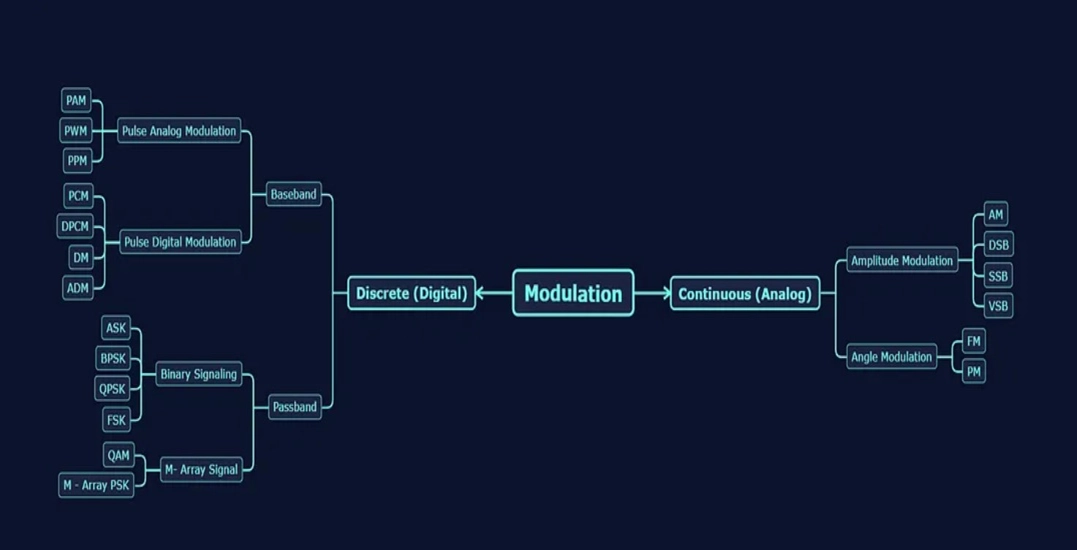
1.2 Types of Modulation
Modulation is a fundamental technique in the field of communication that allows us to adapt information signals for transmission over various mediums. It involves modifying certain characteristics of a carrier signal to encode the information, making it more suitable for efficient and reliable transmission. The three primary types of analog modulation are amplitude modulation (AM), frequency modulation (FM), and phase modulation (PM). Each of these methods distinctly alters the carrier signal, resulting in different advantages and applications. Additionally, in digital communication, modulation techniques like pulse amplitude modulation (PAM), pulse width modulation (PWM), and pulse code modulation (PCM) are used to represent digital data for transmission. Understanding these modulation techniques is essential for designing communication systems tailored to specific requirements and constraints.
Analog modulation techniques
1. Amplitude Modulation (AM)
Amplitude modulation is a fundamental analog modulation technique in which the amplitude of the carrier signal is varied in proportion to the amplitude of the baseband signal. As a result, the carrier signal's strength varies with the information signal. AM is commonly used in radio broadcasting and is relatively simple to implement. However, it is susceptible to amplitude variations due to noise and interference.
2. Frequency Modulation (FM)
Frequency modulation is another analog modulation method where the frequency of the carrier signal is altered based on the instantaneous amplitude of the baseband signal. FM is known for its resilience to amplitude variations, making it suitable for high-fidelity audio transmission and applications where signal quality is crucial, such as FM radio and some forms of two-way radio communication.
3. Phase Modulation (PM)
Phase modulation is the analog modulation technique where the phase of the carrier signal is modified according to the variations in the baseband signal. PM is commonly used in applications like analog television broadcasting and some digital communication systems. It offers resistance to amplitude variations and is especially suitable for situations where precise timing is essential.
Function | Amplitude Modulation | Frequency Modulation | Phase Modulation |
Carrier Frequency | Phase and frequency of carrier signal remain constant | Phase and amplitude of carrier signal remain constant | Amplitude of carrier signal remain constant but frequency is affected |
Mathematical Expression | 𝑣 (𝑡) = [𝐴𝑐 + 𝐴𝑀 cos 2𝜋𝑓𝑚 𝑡]cos 2𝜇𝑓𝑐 𝑡 | 𝑣(𝑡) = 𝐴𝑐 cos (2𝜋𝑓𝐶𝑡) + 𝛽sin (2𝜇𝑓𝑀𝑡)) | 𝑣(𝑡) = 𝐴𝑐 cos 2𝜋𝑓𝐶𝑡 + 𝛽cos (2𝜇𝑓𝑀𝑡) |
Modulation index | Modulation index is the ratio of 𝐴𝑀 𝑎𝑛𝑑 . 𝜇 = 𝐴𝑀 /𝐴c | Modulation index is proportional to modulating signal m(t) as well as modulating frequency fm. 𝛽 = 𝐾𝑓 𝐴𝑀 / 𝑓M | Modulation index is proportional to modulating signal m(t). 𝛽 = 𝐾𝑝𝐴M |
Types | ·Quadrature Amplitude Modulation (QAM) ·Single sideband (SSB) ·Vestigial sideband (VSB) ·Double Sideband Suppressed Carrier(DSB SC) | ·Narrow Band FM modulation index is less than one ·Wideband FM modulation index is greater than one | · PSK - Phase Shift Keying. · BPSK - Binary Phase Shift Keying. · QPSK - Quadrature Phase Shift Keying. · 8 PSK - 8 Point Phase Shift Keying. |
Applications | Computer modems, VHF aircraft radio, and in portable two-way radio , AM Radio and TV broadcasting | FM broadcasting, Radio Broadcasting, Direct Satellite Broadcasting radar, radio and telemetry | Mobile Communications, WiFi, and satellite television |
Digital modulation techniques
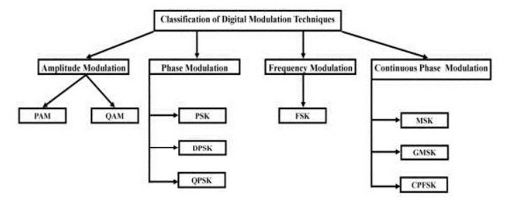
1. Pulse Amplitude Modulation (PAM)
PAM is a digital modulation method in which digital data is represented by varying the amplitude of discrete pulses. It's commonly used in digital communication systems and forms the basis for more complex digital modulation schemes.
2. Pulse Width Modulation (PWM)
PWM is a digital modulation technique that represents data by altering the width of individual pulses within a signal. PWM is often employed in applications like motor control and power electronics.
3. Pulse Code Modulation (PCM)
PCM is a widely used digital modulation method for encoding analog signals into a digital format by sampling the analog signal at regular intervals and quantizing each sample. This technique is integral to digital audio, telecommunications, and digital signal processing.
1.3 Types of Modulators and Demodulators
Modulators are devices or circuits responsible for encoding information onto a carrier signal, while demodulators extract the information from the modulated signal.
· Multiplier Modulators
Multiplier modulators, also known as mixer modulators, are a type of modulator that use a nonlinear device called a mixer to combine the input signal with a high-frequency carrier signal. The mixer produces both sum and difference frequencies of the input signals. The desired modulated signal is obtained by selecting the output at the desired frequency, which corresponds to the sum or difference of the input and carrier frequencies. Multiplier modulators are commonly used in applications like amplitude modulation (AM) and frequency mixing in RF (Radio Frequency) systems.
· Nonlinear Modulators
Nonlinear modulators operate on the principle of using nonlinear components, such as diodes or transistors, to modulate a carrier signal. These devices exploit the nonlinear behavior of their components to produce modulation in various ways. For example, diode-based nonlinear modulators can change the amplitude of the carrier signal in response to the input signal's voltage, resulting in amplitude modulation (AM).
Nonlinear modulators are often found in applications where simple and cost-effective modulation is required, such as low-power RF transmitters and short-range communication systems.
· Switching Modulators
Switching modulators, also known as pulse-width modulators (PWM), employ the technique of pulse-width modulation to encode the input signal onto a carrier. This is done by varying the width or duration of pulses in the modulated signal, where a wider pulse represents a higher amplitude or information-carrying signal. Switching modulators are widely used in digital communication systems, power electronics, and in applications where precise control of output power and energy efficiency is crucial.
· Delta Modulators
Delta modulators are a type of analog-to-digital modulation technique. They quantize the difference between the input signal and the predicted value, resulting in a series of delta-sigma codes. This method is particularly useful in voice coding and low-bit-rate digital communication systems. Delta modulators are employed in telecommunication systems like voice encoding for transmission over digital networks and are often used in voice-over-IP applications.
· Angle Modulators
Angle modulators, also known as phase or frequency modulators, primarily alter the phase or frequency of a carrier signal based on the input signal. These modulators are particularly useful for high-frequency carrier signals and are commonly used in applications like frequency modulation (FM) in broadcasting and telecommunications. Angle modulators are used in FM radio broadcasting, radar systems, and various high-frequency communication systems.
2. Amplitude Modulation
2.1 Fundamentals of Amplitude Modulation
Amplitude Modulation (AM) is a fundamental technique in the field of telecommunications and signal processing, used to transmit information via radio waves. It's a modulation scheme that alters the amplitude of a carrier signal to encode the information, typically in the form of an audio signal, into the carrier wave. AM is one of the simplest and earliest methods of modulating a signal for transmission, and it has historical significance in the development of radio communication.
Amplitude Modulation involves the combination of two signals, the carrier signal and the modulating signal. The carrier signal is a high-frequency waveform, usually a sinusoidal wave, which serves as the carrier for the information to be transmitted. The modulating signal, often an audio signal such as human speech or music, contains the information to be conveyed. By altering the amplitude of the carrier signal in proportion to the instantaneous amplitude of the modulating signal, the information is impressed onto the carrier signal for transmission.
The process of AM involves three key steps,
a. Message Signal (Modulating Signal)
This is the signal that carries the information to be transmitted. It is typically an analog signal, such as an audio waveform.
b. Carrier Signal
The carrier signal is a high-frequency sinusoidal wave, often in the radio frequency (RF) range. This high-frequency carrier signal is modulated by the message signal.
c. Modulated Signal
The modulating signal and carrier signal are combined, and the result is an AM waveform. The amplitude of the carrier signal varies with the instantaneous amplitude of the modulating signal.
Mathematically, AM can be expressed as:
AM(t) = Ac (1 + k . m(t)) cos(2pi fc t)
Where,
AM(t): Amplitude-modulated signal
Ac : Carrier signal amplitude
k : Modulation index
m(t) : Modulating signal
fc : Carrier frequency
Advantages
· AM is relatively simple to implement, both in terms of modulation at the transmitter and demodulation at the receiver. This simplicity was a significant factor in its early adoption and use in radio communication.
· AM receivers are backward-compatible with older AM signals, making it possible to receive and decode signals that were transmitted using this modulation scheme in the past. This backward compatibility has ensured the continued existence of AM radio broadcasts.
· AM signals can travel long distances due to their ability to follow the Earth's curvature and be refracted by the ionosphere. This property makes AM suitable for broadcasting over large geographic areas, especially at night when ionospheric conditions are more favorable.
· AM transmitters and receivers are relatively inexpensive and require less complex equipment compared to more advanced modulation techniques. This cost-effectiveness is especially relevant in regions with limited resources.
· AM signals are better at penetrating obstacles like buildings and other physical structures compared to higher-frequency signals, which are more line-of-sight. This characteristic makes AM suitable for in-building and indoor applications.
Disadvantages
· AM signals are highly susceptible to various forms of interference, such as electrical noise and atmospheric conditions. Amplitude variations due to interference can result in poor signal quality, often leading to audible static and distortion in audio transmissions.
· AM is not bandwidth-efficient. In AM, the carrier signal contains significant power that does not convey any information, as it is solely used for modulation. This inefficiency reduces the number of channels that can be accommodated within the available radio frequency spectrum.
· AM signals can suffer from varying signal quality over different distances and under different atmospheric conditions. Signal fading and distortion are common issues in AM communication, making it less reliable for certain applications.
· AM signals typically have a lower signal-to-noise ratio compared to more advanced modulation techniques like Frequency Modulation (FM) or digital modulation. This means that AM signals are more prone to noise and interference, which can degrade the received signal quality.
· The amount of information that can be transmitted through AM is limited by the modulation index and the available bandwidth. This limitation is a significant drawback for applications that require the transmission of a large amount of data, as AM is primarily used for transmitting audio signals.
· AM uses a significant amount of bandwidth to transmit information, making it less suitable for densely populated radio frequency spectra where efficient bandwidth usage is essential.
Applications
· AM is still used for broadcasting radio stations in various parts of the world.
· AM is used for long-distance communication in maritime and aviation applications.
· In some radar systems, AM is used for target identification.
2.2 Double Sideband, Single Sideband, and Vestigial Sideband Modulations
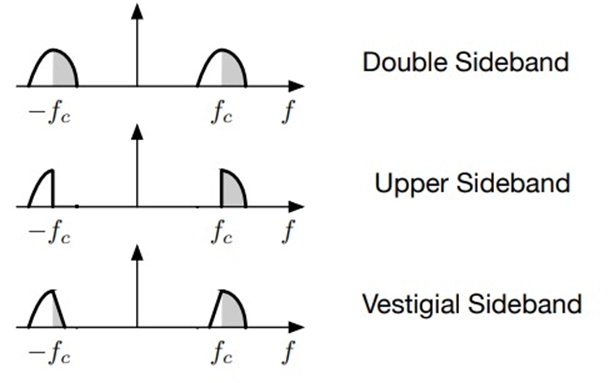
AM can be further categorized into double sideband, single sideband, and vestigial sideband modulations. Each has unique characteristics and applications.
· Double Sideband modulation
Double Sideband-Suppressed Carrier (DSB-SC) modulation is a type of amplitude modulation (AM) where the carrier signal is suppressed, resulting in the transmission of only the sidebands.
In DSB-SC modulation, when the message signal m(t) changes sign (i.e., goes from positive to negative or vice versa), the phase of the modulated signal undergoes a complete reversal. This phase reversal is a distinctive characteristic of DSB-SC modulation. Unlike traditional AM modulation, where the carrier signal is present in the transmitted signal, DSB-SC modulation suppresses the carrier entirely. This makes it difficult to extract the original carrier signal from the received signal. In standard AM, the carrier can be easily recovered through envelope detection, but in DSB-SC modulation, the carrier information is missing, complicating the demodulation process.
DSB-SC modulation is used in certain applications where the carrier recovery isn't essential, such as in some types of analog television broadcasting, where the carrier can be accurately regenerated at the receiver using synchronization information. However, it's important to consider the challenges associated with carrier extraction when using DSB-SC modulation in communication systems.
· Single Sideband modulation
Single Sideband (SSB) modulation is a sophisticated technique employed in radio communication to efficiently transmit one of the sidebands (either upper or lower) along with the message signal, without the carrier. It offers a significant reduction in bandwidth compared to Double Sideband-Suppressed Carrier (DSB-SC) modulation.
SSB modulation is renowned for its spectral efficiency. It transmits only one sideband, which conserves bandwidth. In DSB-SC modulation, both sidebands and the carrier are transmitted, consuming twice the bandwidth of the message signal. In contrast, SSB eliminates one of the sidebands and the carrier.
SSB signals can be reconstructed at the receiver from either the upper sideband (USB) or lower sideband (LSB). This flexibility is advantageous in demodulation because it allows for adapting to various transmission and reception scenarios.
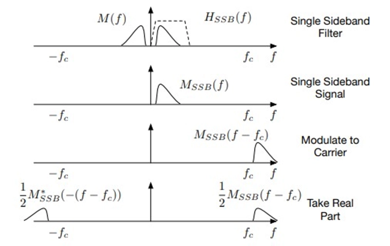
The SSB transmitter utilizes a bandpass filter to select the desired sideband. This filter extracts the sideband while removing the unwanted components, including the carrier and the opposite sideband. To transmit SSB, you can employ a DSB-SC modulator with a narrower bandpass filter. The frequency for the selected sideband is approximately given by:
o For USB: Center frequency (fc) ≈ fc + 1/2B, where B is the bandwidth of the message signal.
o For LSB: Center frequency (fc) ≈ fc - 1/2B.
Here, "fc" represents the carrier frequency. The choice between USB and LSB determines whether the upper or lower sideband is transmitted. The bandpass filter must exhibit a rapid roll-off characteristic to eliminate contributions from the unwanted sideband effectively. This prevents interference from the opposite sideband and carrier, ensuring that only the desired sideband is transmitted.
SSB demodulation can use a DSB-SC demodulator without significant changes. However, the input to the low-pass filter in the demodulation process will differ, depending on whether the received signal is USB or LSB. The demodulation process involves extracting the original message signal from the SSB signal, reversing the modulation process.
In practice, both the transmitter and receiver must agree on whether to use LSB or USB for a specific communication. The choice of sideband depends on the allocated frequency band, regional conventions, and the specific application.
SSB modulation is frequently utilized in amateur radio and shortwave communication. The selection between LSB and USB may vary based on the frequency bands and regional practices. For instance:
o Below 10 MHz: LSB is often used.
o Above 10 MHz: USB is common.
o Exceptions may exist, such as using USB at 5 MHz.
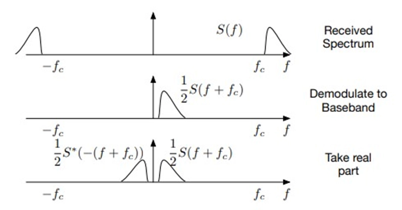
Decoding an SSB signal involves demodulating the received signal back to baseband. A synchronous demodulator is the ideal choice, but in practice, the carrier frequency (fc) is often estimated subjectively by listening to the signal. An error in carrier frequency estimation can significantly impact the quality of the demodulated signal.
o Vestigial Sideband modulations
Vestigial Sideband Modulation (VSB) is a crucial modulation technique used in various applications, particularly where bandwidth efficiency is paramount. Unlike Single Sideband (SSB) modulation, which relies on filtering out one sideband, VSB is engineered to handle signals with components at low frequencies, such as video. Here's an organized and detailed explanation of how VSB works, its applications, and encoding/decoding methods:
Vestigial Sideband Modulation (VSB) is a modulation technique that addresses the challenge of efficient bandwidth utilization, especially for signals like video that contain significant low-frequency components. Unlike audio signals, which can be filtered to remove one sideband effectively, video signals require a different approach. In VSB, a small portion of the unnecessary sideband termed a "vestige," is retained, reducing distortion in the DC (direct current) component.
To create a VSB signal, the process often begins with standard Amplitude Modulation (AM) or Double Sideband-Suppressed Carrier (DSB-SC) modulation. Subsequently, the modulated signal is passed through a sideband shaping filter. This filter shapes the spectrum of the signal and retains a vestige of the unwanted sideband, achieving efficient use of bandwidth.
VSB signals can be designed to support demodulation using either standard AM or DSB-SC demodulation methods, contingent on whether a carrier tone is transmitted. The choice of demodulation technique depends on the specifics of the application and signal design.
Applications of VSB
· VSB modulation, combined with envelope detection, is employed to modulate the image in analog TV signals. In this context, the audio signal is typically modulated using Frequency Modulation (FM). VSB efficiently transmits video content over the airwaves, effectively conserving bandwidth.
· VSB is widely used in MRI systems to reduce the volume of data that needs to be collected. By efficiently encoding and transmitting MRI data, VSB helps improve imaging speed and overall diagnostic capabilities.
The spectrum of a VSB signal can be represented as
ΦVSB(f) = M(f + fc) + M(f - fc) * Hi(f),
Where:
· ΦVSB(f) is the VSB signal spectrum.
· M(f + fc) and M(f - fc) represent the modulated signal on the positive and negative sidebands.
· Hi(f) denotes the shaping filter for the VSB modulator, responsible for controlling the spectral characteristics of the VSB signal.
Various methods can be employed for encoding and decoding VSB signals, especially in modern Software-Defined Radio (SDR) applications. These methods may include complex modulation, the use of different filters, and leveraging Fourier transform symmetry properties to efficiently process VSB signals.
Applications
· VSB modulation is a versatile technique that is not limited to a specific field. Its applications span across diverse domains, from historical analog television systems to cutting-edge medical imaging technologies. As technology evolves, VSB continues to play a pivotal role in achieving efficient transmission and data collection.
3. Angle Modulation
3.1 Nonlinear Modulation
Angle modulation includes both Phase Modulation (PM) and Frequency Modulation (FM). We delve into the principles and applications of nonlinear modulation. Nonlinear modulation under angle modulation is a concept that plays a crucial role in modern communication systems. It pertains to the modulation of signals through phase or frequency modulation in a manner that introduces nonlinearity into the modulation process. This nonlinearity can be intentional or a result of signal distortions or interference.
Nonlinear modulation typically involves either phase modulation (PM) or frequency modulation (FM). In PM, the phase of the carrier signal varies according to the message signal, while in FM, the frequency of the carrier signal is modulated. Nonlinear modulation intentionally introduces nonlinearity into the modulation process. This can result in signal distortion, which can be challenging to demodulate accurately. Nonlinearity can be induced through various means, such as power amplifiers or nonlinear components in the transmitter.
Nonlinear modulation is not commonly used in standard communication systems but can find applications in specific scenarios. One example is in spread spectrum communications, where nonlinear modulation is employed to enhance signal security and robustness.
Demodulating nonlinearly modulated signals can be challenging, as the received signal may undergo significant distortions. Advanced demodulation techniques, such as adaptive equalization and nonlinear compensation, are often required to recover the original message signal accurately. Nonlinear modulation can be susceptible to interference and noise, which may further exacerbate signal distortions. Therefore, managing and mitigating interference is a critical aspect of using nonlinear modulation effectively. Nonlinearity in modulation introduces signal distortions, which can affect the overall signal quality. Understanding the trade-offs between nonlinearity and signal quality is essential in designing communication systems that employ nonlinear modulation.
Nonlinear modulation can be useful in secure communication applications. The inherent nonlinearity can make it more challenging for unintended recipients to demodulate the signal without the appropriate knowledge or key. With advancements in technology, nonlinear modulation techniques are being explored in emerging fields, such as quantum communication, where nonlinearity can play a role in encoding and decoding quantum information.
In nonlinear modulation, careful control of the modulation index (the extent of phase or frequency deviation) is crucial. Adjusting the modulation index can help manage signal distortions and improve demodulation performance.
3.2 Relationship between PM and FM
We explore the connection between Frequency Modulation (FM) and Phase Modulation (PM) and understand their interplay in communication systems.
Phase Modulation
Phase Modulation (PM) is a fundamental modulation technique commonly used in communication systems, particularly in applications where the variation in the phase of a carrier signal encodes the message signal. Here's an organized and expanded explanation of how PM works, its impact on instantaneous frequency, and its relationship with signal bandwidth:
In Phase Modulation (PM), the phase of the carrier signal is linearly varied with the message signal, m(t). Mathematically, this is expressed as:
θ(t) = 2πfct + kpm(t)
Where,
θ(t) = Phase of the modulated signal.
2πfct = Carrier phase at frequency fc.
k = Modulation index that controls the degree of phase variation.
m(t) = Message signal, which causes phase modulation.
This modulation process results in a transmitted signal, ϕPM(t), given by,
ϕPM(t) = cos [2πfct + kpm(t)]
The instantaneous frequency of the PM signal, denoted as ωi(t), is a critical parameter. It represents how quickly the phase changes over time. Mathematically, it can be expressed as the derivative of the phase with respect to time,
ωi(t) = dθ/dt = 2πfc + kpm'(t)
Here,
ωi(t) is the instantaneous angular frequency.
m'(t) is the derivative of the message signal m(t), indicating the rate of change of the message signal.
If the message signal, m(t), varies rapidly, it leads to larger deviations in frequency. In other words, the more significant the changes in the message signal, the more pronounced the variations in the instantaneous frequency. This characteristic is essential in understanding how phase modulation can convey information.
The bandwidth of a PM signal is primarily determined by the rate of change of the message signal, m'(t). In a similar fashion to Amplitude Modulation (AM), where bandwidth depends on the rate of change of the envelope of the message signal, in PM, the rate of change of the message signal's phase controls the bandwidth. This means that the faster the phase of the message signal changes, the wider the bandwidth of the modulated signal.
Applications of Phase Modulation
Phase Modulation is used in various communication systems, including analog and digital modulation schemes. It is a key component in frequency modulation (FM) and is often employed in techniques like frequency-shift keying (FSK) used in digital data transmission.
Advantages of PM
· Phase modulation is less susceptible to amplitude variations and noise than amplitude modulation (AM), making it suitable for high-quality audio and communication applications.
· It is commonly used in applications where signal quality and signal-to-noise ratio are crucial.
Frequency Modulation
Frequency Modulation (FM) is a fundamental modulation technique used in communication systems. It involves the linear variation of the frequency of a carrier signal based on the message signal, m(t). Here is an organized and detailed explanation of how FM works, its impact on signal bandwidth, and its relation to phase modulation:
In Frequency Modulation (FM), the instantaneous frequency of the carrier signal varies linearly with the message signal, m(t). This relationship can be mathematically expressed as,
ωi(t) = 2πfc + kfm(t)
ωi(t) = Instantaneous angular frequency
2πfc = Carrier frequency
K = modulation index
m(t) = Message signal
The FM signal, ϕFM(t), is defined as,
ϕFM(t) = cos [2πfc + kfm(t)t]
The bandwidth of an FM signal is determined by two main factors:
1. The amplitude of kfm(t): The extent of frequency deviation (modulation index k) directly influences the bandwidth. Larger deviations lead to wider bandwidths.
2. The bandwidth of the message signal, m(t): The spectrum of the message signal m(t) also contributes to the overall bandwidth of the FM signal. The more extensive the message signal's bandwidth, the wider the resulting FM signal.
The instantaneous phase, θ(t), of an FM signal can be represented as an integral of the instantaneous frequency ωi(t) over time. Mathematically, it is given as:
θ(t) = ∫ [2πfc + kfm(t)] dt
This integral describes how the phase of the FM signal accumulates over time and is a key element in understanding the behavior of FM-modulated signals.
Applications of FM
Frequency Modulation is widely used in various communication systems and broadcasting, particularly in applications where noise resistance, signal quality, and wide signal bandwidth are important. It is the basis for frequency modulation broadcasting, such as FM radio, and is also employed in advanced digital modulation schemes like frequency-shift keying (FSK) used in data transmission.
Advantages of FM
· FM is less susceptible to amplitude variations and noise than Amplitude Modulation (AM), making it ideal for high-fidelity audio transmission.
· It provides a constant amplitude signal, resulting in consistent signal quality.
Relationship between FM and PM
The relationship between Frequency Modulation (FM) and Phase Modulation (PM) is an important concept in modulation theory, highlighting the duality between these two modulation techniques.
The bandwidth of an FM signal is primarily determined by the amplitude of kfm(t), which controls the extent of frequency deviation. However, an often less obvious factor is the bandwidth of the message signal, m(t). A wider bandwidth message signal will result in a wider overall bandwidth for the FM signal.
One interesting aspect is that phase modulation of the message signal, m(t), results in frequency modulation of its derivative, m'(t). This relationship highlights the duality between FM and PM. Similarly, frequency modulation of the message signal, m(t), leads to phase modulation of the integral of m(u) du over time, denoted as Rm(u) du.
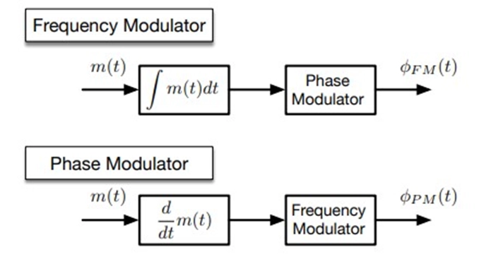
The critical insight is that we can achieve both frequency modulation and phase modulation by using either a frequency modulator or a phase modulator. This interchangeability underscores the fundamental connection between FM and PM.
Direct digital synthesis (DDS) chips and digital modulation techniques provide practical ways to perform FM and PM and switch between them as needed. These technologies have broad applications in modern communication systems and signal processing.
3.3 Generating FM Waves
Generating Frequency Modulation (FM) waves involves the conversion of a baseband message signal, typically in the audio frequency range, into an FM signal by varying the instantaneous frequency of a carrier wave.
In FM, the key concept is that the instantaneous frequency of the carrier wave changes in direct proportion to the amplitude of the message signal. This means that the rate of change of the carrier frequency is controlled by the amplitude of the message signal at any given time.
Generating FM waves can be accomplished using various techniques and circuits. Here are the primary methods:
1. Direct FM Generation
This method directly varies the frequency of an oscillator with the message signal. One of the most common approaches is to use a voltage-controlled oscillator (VCO). A VCO is driven by a voltage that is proportional to the amplitude of the message signal. As the message signal's amplitude changes, the VCO's output frequency varies accordingly, creating an FM signal. This method is relatively straightforward and can produce high-quality FM signals.
2. Indirect FM Generation (Phase-Locked Loop - PLL)
An indirect approach to generating FM is to first convert the message signal into a phase-modulated signal, and then use a phase-locked loop to generate the FM signal. A phase modulator modulates the carrier's phase based on the message signal. The phase-locked loop locks onto this phase-modulated signal and produces an output with a frequency that varies with the phase modulation. This method is particularly useful when precise frequency control and stability are required.
3. Digital FM Generation
In the digital domain, FM signals can be generated by directly manipulating the phase of a carrier signal at a high sampling rate. This approach is often used in software-defined radio (SDR) and digital signal processing (DSP) systems. The digital signal processor performs the necessary phase adjustments in real-time based on the message signal.
· Key Components in FM Generation
o Message Signal Source: This is the source of the baseband signal, which could be an audio signal from a microphone or an electronic signal from a data source.
o Modulator: The modulator applies phase modulation to the carrier signal based on the message signal.
o Carrier Signal Source: The source of the carrier signal, typically a high-frequency oscillator.
o Voltage-Controlled Oscillator (VCO): In direct FM generation, a VCO is commonly used to generate the FM signal. A voltage controlled oscillator generates a signal whose instantaneous frequency proportional to an input m(t).
o Phase-Locked Loop (PLL): In indirect FM generation, a PLL is employed to lock onto the phase-modulated signal and generate the FM signal.
· Applications of FM Waves
FM waves are widely used in FM radio broadcasting, where the message signal contains audio information. They are also used in various wireless communication systems, radar, and satellite communication.
3.4 Demodulation of FM Signals
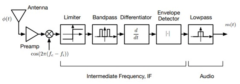
Demodulation of Frequency Modulated (FM) signals is a critical step in the reception and extraction of information from FM-modulated signals. Various methods can be employed for FM demodulation, many of which involve differentiation or the manipulation of the signal to recover the original message signal. Some common demodulation techniques are mentioned below.
1. Differentiator
A differentiator is a simple electronic circuit that calculates the rate of change (derivative) of the FM signal. This operation emphasizes the variations in the signal, which correspond to the variations in frequency due to the message signal.
2. Slope Detection
Slope detection is a technique that focuses on measuring the steepness or slope of the FM signal's waveform. The slope at any point directly relates to the instantaneous frequency, allowing for signal demodulation.
3. Frequency-Selective Filter
Using a frequency-selective filter can help extract the message signal from the FM waveform. By filtering out the carrier frequency component and retaining the frequency variations caused by the message signal, the original information can be obtained.
4. RC High-Pass Filter
A high-pass filter can be employed to emphasize the variations in the FM signal that contain the message information. The frequency response of the filter depends on the values of resistance (R) and capacitance (C).
5. RLC Circuit with Carrier Frequency ωc < ω0
An RLC circuit with the carrier frequency ωc less than the resonant frequency ω0 of the circuit can be used for FM demodulation. The circuit's response to the FM signal extracts the message signal.
6. Zero-Crossing Detectors
Zero-crossing detectors identify the points in the FM signal where the signal crosses the zero voltage level. The timing of these zero crossings corresponds to the variations in frequency and can be used to recover the message signal.
7. Phase-Locked Loop
A phase-locked loop (PLL) is a sophisticated electronic circuit used for demodulating FM signals. It works by locking onto the phase of the carrier signal, tracking its changes, and deriving the message signal. PLL demodulation is highly accurate and commonly used in FM demodulators.
3.5 FM Broadcasting System
FM broadcasting is a widely used and versatile communication system that goes beyond simple monaural (mono) audio transmissions. In the context of the provided text, let's explore the components and features of an FM broadcasting system:
1. Wideband FM (WBFM)
- FM broadcasting typically employs Wideband FM (WBFM) to transmit audio signals. WBFM provides superior audio quality and noise resistance compared to Amplitude Modulation (AM).
2. Stereo Broadcasting
FM broadcasting is commonly used for stereo audio transmission. This stereo signal is a combination of two audio channels: Left (L) and Right (R).
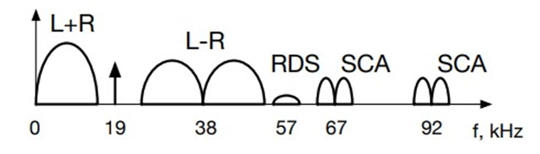
3. Baseband Components
In stereo FM broadcasting, the audio components are distributed across the frequency spectrum as follows:
o Left+Right (L+R) components are centered in the middle of the spectrum.
o Left-Right (L-R) components are offset by 38 kHz from the carrier frequency.
o A 19 kHz pilot tone is used as a reference signal for stereo demodulation.
4. Additional Data and Signals
FM broadcasting systems may include other components and data signals, such as:
o Radio Data System (RDS) digital signal at 57 kHz: RDS is used to transmit additional information to receivers, including station identification, program information, and traffic updates.
o Subsidiary Communications Authorization (SCA) signals at 67 and 92 kHz: SCA is used for specialized content, such as subcarriers for background music, foreign-language programming, or data services.
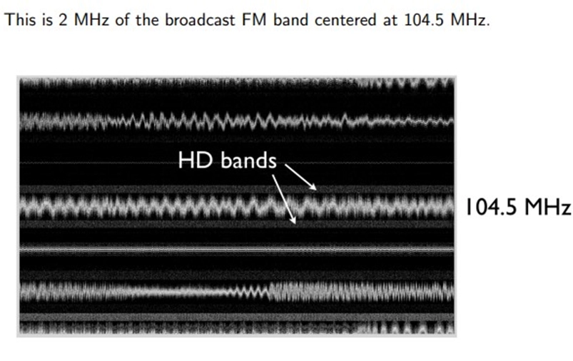
o High Definition (HD) Bands: Some FM broadcasting systems can incorporate up to four high-definition audio bands, which offer higher-quality audio than traditional FM signals.
FM broadcasting is renowned for its high-quality audio, stereo capabilities, and the ability to convey additional information, making it a preferred choice for radio stations, music broadcasting, news, and a variety of multimedia applications. The availability of these components and features enhances the listening experience and provides broadcasters with versatile means to deliver content to their audience.
· Broadcast FM Signal Spectrogram
A spectrogram is a graphical representation of how the frequencies present in a signal change over time. In the context of a broadcast FM signal, a spectrogram provides a time-frequency analysis. It displays how the signal's frequency components evolve over the duration of the signal. The x-axis represents time, the y-axis represents frequency, and the color or intensity represents the strength of those frequencies at different time points.
Spectrograms are typically generated using mathematical techniques like the Fast Fourier Transform (FFT) to break down the signal into its frequency components. They are used in signal analysis to identify characteristics of FM broadcasts, such as signal quality, station identification, and interference. Radio engineers and researchers use spectrograms to assess FM broadcast performance and diagnose issues.
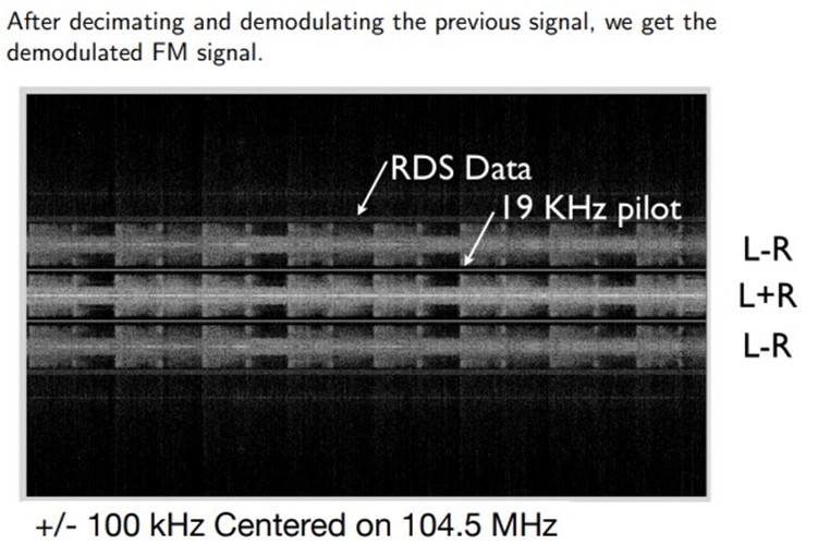
· Broadcast FM Signal Demodulated
Demodulation is the process of extracting the original message signal from a modulated carrier signal. In the case of broadcast FM signals, this means recovering the audio content from the frequency-modulated carrier wave. Frequency demodulation is used in FM broadcasting to convert the varying frequency of the carrier signal back into the original audio signal.
This is typically achieved through a discriminator or detector circuit that calculates the rate of change of the phase or frequency of the signal. The resulting signal is the original audio signal that was used to modulate the carrier and can then be amplified and played through speakers for listeners.
4. Pulse Code Modulation/Pulse Amplitude Modulation
4.1 Sampling Theorem and Its Applications
Sampling theorem plays a crucial role in Pulse Code Modulation (PCM) and Pulse Amplitude Modulation (PAM). We discuss its significance and applications.
A signal with a bandwidth of B can be precisely recreated from samples obtained at any rate R>2B, according to the sampling theorem.
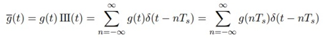
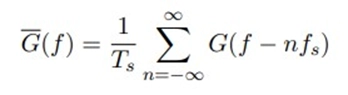
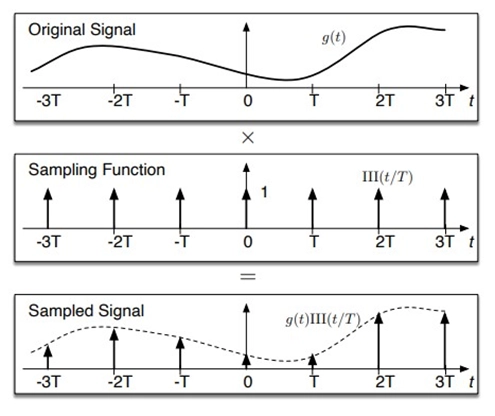
Mathematically, sampling can be accomplished by multiplying by an impulse train. This is how the unit impulse train is described,
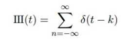
The III or comb function is another name for the unit impulse train. A signal g(t) is obtained by evenly sampling it at intervals Ts.
Fourier transform of III(t),
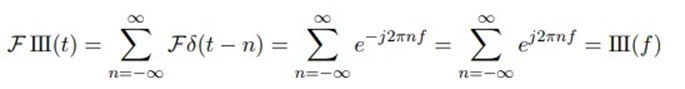
At non-integer frequencies, the complex exponentials cancel, but at integer frequencies, they combine to form an impulse.
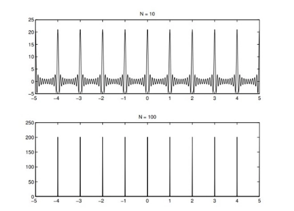
The complex exponential sum of all multiples of the fundamental frequency can be used to represent the impulse train III(t/Ts), which is periodic with period Ts.
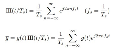
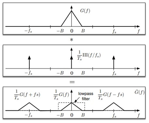
By the frequency shifting property,
An impulse train performs convolution in the frequency domain sampling.
Sampling of a Cosine Signal,
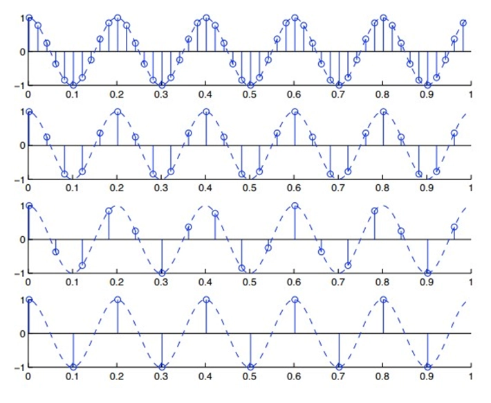
Sampling of a cosine signal involves discretely capturing the values of a continuous cosine wave at regular intervals. This process, guided by the Nyquist-Shannon theorem, requires a sampling rate (Fs) at least twice the frequency of the cosine signal (2*f) to avoid aliasing. The result is a discrete sequence of amplitudes that can be digitally processed and, when needed, reconstructed to approximate the original continuous signal. This fundamental technique is essential in applications such as digital audio processing and wireless communication, allowing for the conversion of analog signals into digital format for further analysis and transmission.
What is aliasing?
Aliasing is a phenomenon that occurs in signal processing when the sampling rate (sampling frequency) used to discretely capture a continuous signal is too low to accurately represent the original signal. When aliasing happens, spectral replicas or unwanted components of the signal overlap or "fold" into the frequency spectrum, causing a distortion of the signal. In essence, it results in a loss of information and the inability to faithfully reconstruct the original signal. Aliasing is a well-known issue, and it can be mitigated by increasing the sampling rate or using anti-aliasing filters to remove high-frequency components before sampling. This is a fundamental concept in signal processing, particularly in applications like digital audio and image processing.
The spectral copies overlap when the sampling rate is too low,
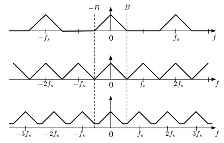
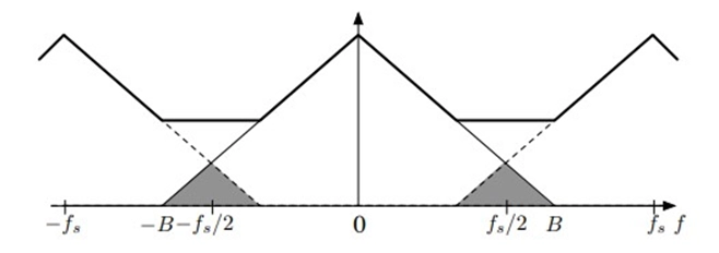
The shaded frequencies are unclear and overlap. High-frequency oscillations turn into high-frequency oscillations.
4.2 PCM and PAM
PCM and PAM are digital modulation techniques. In here we discuss their principles and applications, including digital telephony.
PCM
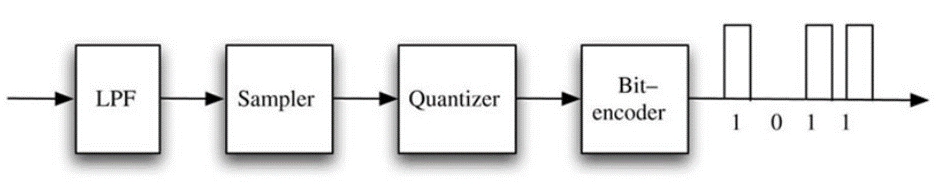
Pulse Code Modulation (PCM) is a digital encoding method used to represent analog signals by a sequence of binary digits (pulses). The text you provided contains key elements of PCM:
In PCM, the width and spacing of these binary pulses are kept constant, ensuring uniform intervals between samples of the analog signal. This uniformity simplifies the process of encoding and decoding. A small set of binary values is used to represent the analog signal. Typically, PCM employs only two pulse values, which correspond to 0 and 1.
The quantization process in PCM results in discrete binary values that represent the amplitude of the analog signal. These binary values can be produced using different coding schemes, such as unsigned linear, two's complement, or A-law and µ-law encoding.

In this method, the signal values are quantized to a range of values from 0 to ∆ν, with 2^m possible values (where "m" is the number of bits used for encoding). This encoding method allows for signed representation, ranging from -∆ν/2^(m-1) to ∆ν/2^(m-1), covering both positive and negative values.
These methods use logarithmic encoding to offer a more extensive dynamic range for encoding signal values, particularly useful for audio applications.
The precision of the quantization process in PCM is directly related to the number of bits used for encoding. A higher number of bits provides finer quantization and better signal fidelity.
PCM-encoded binary values can be reconstructed into an analog signal using a digital-to-analog converter (DAC). The DAC converts the binary sequence back into a continuous waveform, allowing the reproduction of the original analog signal.
PCM is widely used in various applications, particularly in digital audio encoding and telecommunications, due to its simplicity and high fidelity. The choice of PCM parameters, such as the number of quantization levels (determined by the number of bits), is critical in determining the signal quality and the amount of data required for transmission or storage.
PAM
Pulse Amplitude Modulation (PAM) is a digital encoding method used to represent analog signals by a sequence of discrete pulses, where the amplitude of each pulse represents the value of the analog signal. Here's a description of PAM using the concepts you provided:
In PAM, each pulse has a fixed amplitude and represents a specific sample of the analog signal. The pulse amplitudes remain constant, which simplifies encoding and decoding processes.
PAM uses a restricted set of pulse amplitudes to represent the analog signal. The number of possible amplitudes corresponds to the quantization levels and is determined by the bit depth used for encoding.
· Unsigned Linear: In PAM, the signal values are quantized into a set of amplitudes, ranging from 0 to ∆A, with 2^m possible amplitude levels (where "m" is the number of bits used for encoding).
· Two's Complement: Similar to PCM, two's complement encoding in PAM enables signed representation, covering both positive and negative amplitude values within a specified range.
The precision of PAM encoding is directly related to the number of bits used for representation. A higher number of bits results in finer quantization and improved signal fidelity.
The PAM-encoded pulse amplitudes can be converted back into an analog signal using a digital-to-analog converter (DAC). The DAC reconstructs the analog signal from the discrete amplitudes, allowing the reproduction of the original continuous signal.
Pulse Amplitude Modulation is commonly used in various applications, including telecommunications, data transmission, and analog-to-digital conversion processes. The choice of the number of quantization levels, determined by the bit depth, plays a crucial role in determining the signal quality and the amount of data required for transmission or storage, similar to PCM.
4.3 Advantages of Digital Communication
· Digital signals are less susceptible to noise interference and distortion, ensuring more reliable data transmission in challenging environments.
· Digital communication enables video conferencing, saving time, money, and effort. It provides a means to engage in face-to-face meetings with people at remote locations, facilitating better communication through visual cues and expressions.
· Implementing digital communication is generally more cost-effective and straightforward compared to analog methods. It also benefits from advanced integrated circuit (IC) technologies.
· Digital communication is widely used in military applications, where secure and reliable data transmission is crucial.
· Digital communication incorporates channel coding techniques that simplify the correction and detection of errors, enhancing the overall data integrity.
· Digital signals are easy to store and retrieve, making them suitable for applications that require data preservation and recovery.
· The configuration process for digital signals is simpler than that of analog signals, offering flexibility in customizing communication systems.
· Most digital circuits employ common encoding techniques, allowing for the use of similar devices across multiple processes.
· The probability of cross-talk, or signal interference between communication channels, is significantly lower in digital communication.
· Hardware implementation in digital communication is more flexible, offering versatility in designing communication systems.
· To mitigate signal jamming, digital communication utilizes the spread spectrum technique, enhancing security and reliability.
· Digital communication supports audio conferencing, enabling remote discussions with individuals or groups, saving time, effort, and expenses.
4.4 Disadvantages/Limitations of Digital Communication
· Digital communication systems often require higher power consumption, which can be a limitation in energy-sensitive applications.
· Synchronous modulation in digital communication necessitates precise timing and synchronization, which can add complexity to system design.
· Sampling processes in digital communication introduce sampling errors, affecting the accuracy of the reconstructed signal.
· Digital communication typically requires more transmission bandwidth due to higher data rates resulting from analog-to-digital conversion. This aspect can pose challenges in bandwidth-constrained scenarios.
· A significant limitation is the need for frequent analog-to-digital conversion, which can be computationally intensive and may require high-speed converters.
· In complex systems, there is a potential for miscommunication, particularly if users do not have a clear understanding of the technology.
4.5 Quantizing
Quantizing is a key step in PCM, affecting signal accuracy. We explore quantization techniques and their impact. In Pulse Code Modulation (PCM), there are primarily two types of quantization methods:
1. Uniform Quantization
Uniform quantization is the most straightforward and commonly used method in PCM. It divides the range of possible analog signal amplitudes into a fixed number of equally spaced levels or bins. Each sample is assigned to the nearest quantization level, effectively rounding it to the closest value. Linear quantization is used in most PCM systems, where the quantization levels are evenly spaced, making it simpler to implement.
A nonlinear time-invariant system is the ideal uniform quantizer. If the breadth v has L = 2N+1 levels,
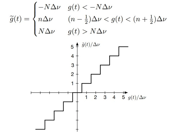
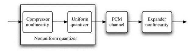
2. Nonuniform Quantization
Nonuniform quantization, also known as companding, is used in certain applications to improve the signal-to-noise ratio. Companding stands for "compression" and "expansion." It involves compressing the dynamic range of the signal during encoding and expanding it during decoding.
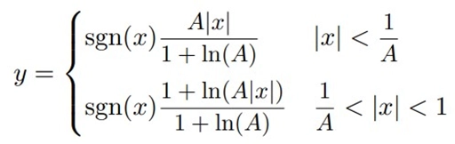
Quantization intervals are widened by non-uniform quantizers as value magnitude increases. The logarithmic curve is implied by an interval proportional to the value.
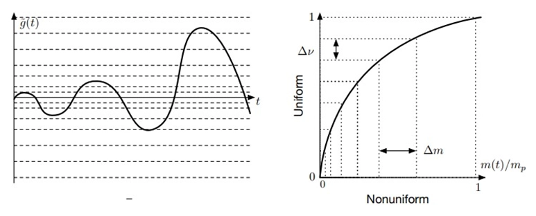
Companding techniques like A-law and µ-law are used in telecommunications, particularly for voice signal encoding. These methods assign more quantization levels to lower-amplitude signals, which is particularly useful in preserving the quality of low-amplitude voice signals while efficiently using the available bits for encoding.
Comparison of µ-law and A-law:-
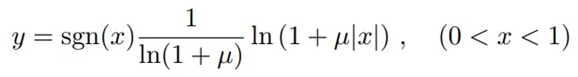
1. µ-law
· µ-law companding is primarily used in North America and Japan.
· It is a logarithmic companding algorithm that compresses the dynamic range of the input signal.
· In µ-law, the quantization levels are denser for low-amplitude signals and less dense for high-amplitude signals. This means that more bits are allocated to encode lower-amplitude components, preserving signal quality.
· µ-law companding provides better performance for encoding voice signals, particularly when dealing with quiet or low-level speech.
2. A-law
· A-law companding is predominantly used in Europe and most other parts of the world.
· It is another logarithmic companding algorithm that compresses the input signal's dynamic range.
· In A-law, the quantization levels are denser for low-amplitude signals and less dense for high-amplitude signals, similar to µ-law.
· A-law companding is preferred in many international telecommunications standards, and it offers slightly different performance characteristics compared to µ-law.
Both µ-law and A-law companding techniques serve the same purpose: to compress the dynamic range of an analog signal for more efficient quantization. The choice between the two often depends on regional or system-specific standards.
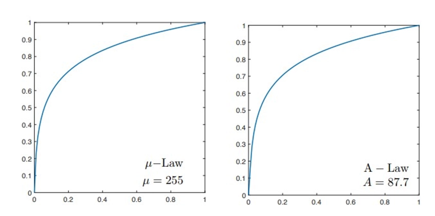
The major difference between the two lies in the constants used in their companding formulas (µ for µ-law and A for A-law). These constants affect the quantization characteristics, making µ-law more commonly used in North America and Japan, while A-law is widely adopted in Europe and other regions.
In terms of voice signal encoding, both µ-law and A-law are effective at preserving audio quality by allocating more quantization levels to lower amplitude speech components. The choice between them is largely based on regional standards and system compatibility.
Quantization error
Quantization error, also known as quantization distortion or quantization noise, is a type of error or distortion that occurs in the process of quantizing a continuous analog signal into a discrete digital representation. This error arises because, in quantization, it's impossible to represent the infinite number of possible analog values exactly with a finite number of digital levels (quantization levels or bins).
Quantization error occurs due to the following reasons,
· In digital systems, the continuous range of analog values must be approximated by a finite set of discrete values. The difference between the actual analog value and its quantized digital representation leads to quantization error.
· Each analog sample is mapped to the nearest available quantization level. The difference between the original analog value and the quantized value is the quantization error.
· The size of the quantization intervals (the step size between quantization levels) determines the maximum possible error. Smaller step sizes result in smaller quantization errors but require more bits to represent each sample.
Quantization error can take the form of noise in the digital signal. This noise has both deterministic and random components. The deterministic component arises due to the fixed quantization step size, while the random component is the result of quantization rounding and can be modeled as additive white noise. As the number of quantization levels increases (higher bit depth), the quantization error decreases, resulting in a more faithful representation of the original analog signal.
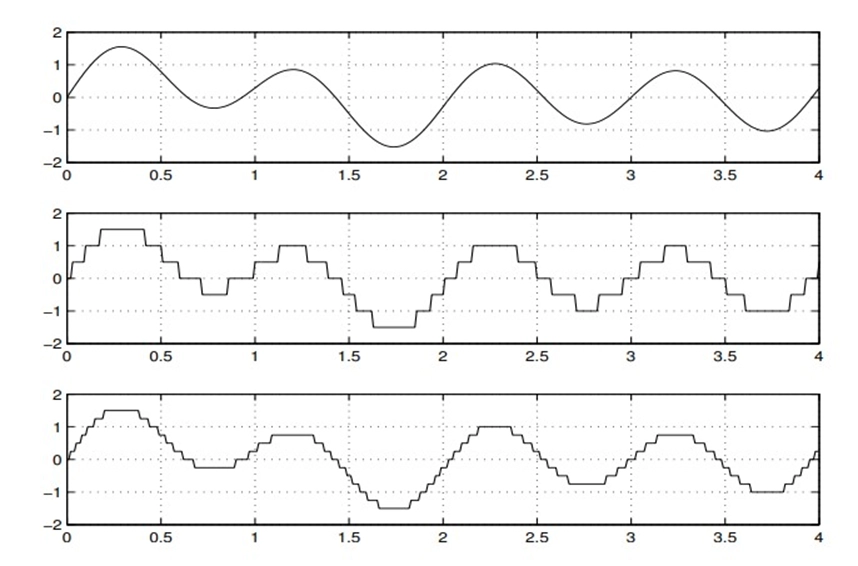
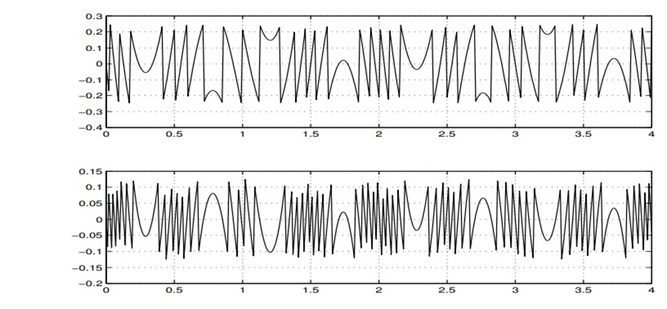
Example:- Signal quantized into levels of 4 and 16.
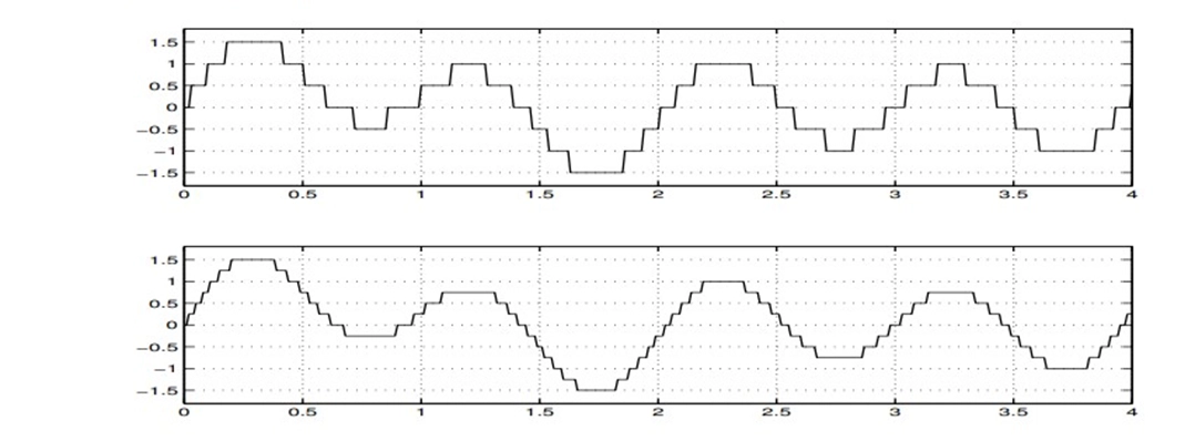
Quantization error when quantizing to levels of 4 and 16,
5. References
[1] | B. Lathi and Z. Ding, "MODERN DIGITAL AND ANALOG COMMUNICATION SYSTEMS," New York, OXFORD UNIVERSITY PRESS, 2019, p. 1025. |
[2] | J. G. Proakis, "Digital Communications," Beijing, House of Electronics Industry, p. 1015. |
[3] | W. Tam, C. Francis and C. Tse, "Digital communications with chaos_ multiple access techniques and performance-Elsevier," 2007, p. 237. |
[4] | G. Miao, "Signal Processing," Norwood, ARTECH HOUSE, 2007, p. 533. |
[5] | L. Couch, "DIGITAL AND ANALOG COMMUNICATION SYSTEMS," Florida, Pearson, 2013, p. 789. |
[6] | . R. BAINES, "Modulation and Demodulation," IEEE Communications Magazine, vol. 33, no. 9 September 1995, p. 54, 1995. |
[7] | S. Jangra and R. Kumar, "Digital Modulation Techniques Using," IJCSC, vol. 6, no. Sep 2015, p. 5, 2015. |
[8] | MIT, "Modulation and Demodulation," Modulation and Demodulation, p. 23, 11 April 2012. |
[9] | J. Mistry, "Simulating modulation & demodulation techniques in MATLAB," Medium, 2020. |
[10] | J. M. Pauly, " Modulators, Receivers, AM, and SSB," Stanford, 2021. |
[11] | R. Anderson and J. Salz, "Spectra of Digital FM," Bell Syst Tech. |
[12] | C. Sundberg and T. Aulin, "Digital Phase Modulation," New York, 1986. |
6. Appendices
Appendix A: Glossary of terms
1. Baseband Communication: The transmission of digital or analog signals without modulation onto a carrier frequency.
2. Carrier Communication: A communication method that involves modulating a high-frequency carrier signal with information-bearing signals.
3. Modulation: The process of varying one or more properties (amplitude, frequency, or phase) of a carrier signal following an information signal to transmit data.
4. Demodulation: The process of extracting the original information signal from a modulated carrier signal.
5. Amplitude Modulation (AM): A modulation technique where the amplitude of the carrier signal is varied in proportion to the instantaneous amplitude of the modulating signal.
6. Double Sideband (DSB) Modulation: A type of AM where both the upper and lower sidebands are transmitted.
7. Single Sideband (SSB) Modulation: A type of AM where only one sideband (either upper or lower) is transmitted to reduce bandwidth.
8. Vestigial Sideband (VSB) Modulation: A variation of AM where a portion of one sideband is transmitted to achieve a compromise between bandwidth and signal quality.
9. Angle Modulation: A modulation technique that involves varying the phase (Phase Modulation, PM) or frequency (Frequency Modulation, FM) of the carrier signal.
10. Phase Modulation (PM): Modulating the phase of a carrier signal in proportion to the modulating signal.
11. Frequency Modulation (FM): Modulating the frequency of a carrier signal in proportion to the modulating signal.
12. FM Broadcasting System: A system that uses frequency modulation to transmit audio signals for broadcasting.
13. Pulse Code Modulation (PCM): A method of digitally encoding analog signals, often used in telephony.
14. Pulse Amplitude Modulation (PAM): A modulation technique where the amplitude of a series of pulses is varied to represent analog data.
15. Sampling Theorem: The Nyquist-Shannon theorem, states that for faithful reproduction of an analog signal, it must be sampled at a rate at least twice its highest frequency component.
16. Quantization: The process of mapping analog signal amplitudes to discrete digital values.
17. Digital Telephony: Telecommunication using digital signals for voice transmission.
Appendix B: Simulation code and Frequency Spectrum illustrations
1. Matlab Code to simulate Amplitude Modulation
1clc; 2clear all; 3close all; 4 5Ac=2; %carrier amplitude 6fc=0.5; %carrier frequency 7Am=.5; %message signal amplitude 8fm=.05; %message signal frequency 9Fs=100; %sampling rate/frequency10 11ka=1;%Amplitude Sensitivity12 13t=[0:0.1:50];%defining the time range & disseminating it into samples14ct=Ac*cos(2*pi*fc*t); %defining the carrier signal wave15mt=Am*cos(2*pi*fm*t); %defining the message signal16AM=ct.*(1+ka*mt); %Amplitude Modulated wave, according to the standard definition17 18subplot(3,1,1);%plotting the message signal wave19plot(mt);20ylabel('Message signal');21 22subplot(3,1,2); %plotting the carrier signal wave23plot(ct);24ylabel('carrier');25 26subplot(3,1,3); %plotting the amplitude modulated wave27plot(AM);28ylabel('AM signal');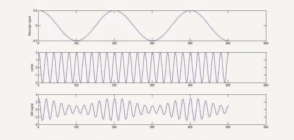
2. Matlab Code to simulate Frequency Modulation
1clc 2clear all 3close all 4t = 0:0.001:1; %upto 1000 samples 5vm = input('Enter Amplitude (Message) = '); 6vc = input('Enter Amplitude (Carrier) = '); 7fM = input('Enter Message frequency = '); 8fc = input('Enter Carrier frequency = '); 9m = input('Enter Modulation Index = ');10msg = vm*sin(2*pi*fM*t);11subplot(3,1,1); %plotting message signal12plot(t,msg);13xlabel('Time');14ylabel('Amplitude');15title('Message ');16 17carrier = vc*sin(2*pi*fc*t);18subplot(3,1,2); %plotting carrier signal19plot(t,carrier);20xlabel('Time');21ylabel('Amplitude');22title('Carrier Signal');23 24y = vc*sin(2*pi*fc*t+m.*cos(2*pi*fM*t));25subplot(3,1,3);%plotting FM (Frequency Modulated) signal26plot(t,y);27xlabel('Time');28ylabel('Amplitude');29title('FM Signal');Sample MATLAB Input:
1Enter Amplitude (Message) = 52Enter Amplitude (Carrier) = 53Enter Message frequency = 84Enter Carrier frequency = 1005Enter Modulation Index = 10
Appendix C: Acronyms and Abbreviations
This appendix provides a list of acronyms and abbreviations used throughout the report to help readers quickly understand and reference key terms and concepts.
AM: Amplitude Modulation
DSB: Double Sideband
SSB: Single Sideband
VSB: Vestigial Sideband
PM: Phase Modulation
FM: Frequency Modulation
PCM: Pulse Code Modulation
PAM: Pulse Amplitude Modulation
BW: Bandwidth
SNR: Signal-to-Noise Ratio
IF: Intermediate Frequency
RF: Radio Frequency
THD: Total Harmonic Distortion
ADC: Analog-to-Digital Converter
DAC: Digital-to-Analog Converter
BER: Bit Error Rate
PSK: Phase Shift Keying
FSK: Frequency Shift Keying
Nyquist Theorem: Nyquist-Shannon Sampling Theorem
MSB: Most Significant Bit
LSB: Least Significant Bit
ADC: Analog-to-Digital Converter
DAC: Digital-to-Analog Converter
PWM: Pulse Width Modulation
SPWM: Sinusoidal Pulse Width Modulation
QAM: Quadrature Amplitude Modulation
FCC: Federal Communications Commission
WCDMA: Wideband Code Division Multiple Access
CDMA: Code Division Multiple Access
QPSK: Quadrature Phase Shift Keying
PCM: Pulse Code Modulation