
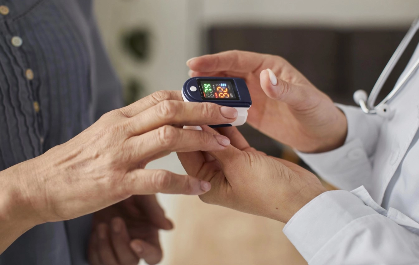
A pulse oximeter is a vital medical device that measures oxygen saturation percentage using red and infrared light. This device operates on the fundamental principle that oxygenated blood absorbs more infrared rays compared to deoxygenated blood. By precisely quantifying the light absorbed, a pulse oximeter calculates the oxygen saturation level, often referred to as the oxygen saturation index or SpO2. Explore this informative guide to gain a deeper understanding of how pulse oximeters work and their critical role in healthcare monitoring.
Working Process
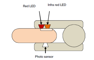
Pulse oximeters, essential healthcare devices, employ two light-emitting diodes (LEDs) to shine light through the skin - one red and one infrared. These LEDs are thoughtfully placed on a probe, which can be comfortably positioned on the finger, earlobe, or toe of the individual. As this light traverses through the skin, a portion of it is absorbed by the blood. The degree of light absorption hinges on the blood's oxygen saturation. Additionally, the device incorporates a photodetector, situated on the same probe as the LEDs, to gauge the quantity of light that successfully penetrates the skin.
By leveraging the data from the photodetector, the device meticulously calculates the oxygen saturation of the blood. This calculation involves a comparison between the light absorbed by the blood and the light transmitted through the skin. The resulting oxygen saturation level is then presented as a percentage on the device's screen. Typically, a healthy individual exhibits an average oxygen saturation level ranging from 95% to 100%. Should the readings fall below this range, it may signal insufficient oxygen intake, possibly indicating underlying medical conditions like COPD or asthma.
Project
Usually, pulse oximeters are made using a MAX 30100 sensor which will cost more than the components used in my project. Therefore I have reduced the production cost by using some simple electronic components and Arduino.
Components
Resistors (10K, 4.7K*2), Photodiode, IR LED, Red LED, LM 7805, BC547 transistors, OLED display, Arduino pro mini, 9V Battery
Circuit diagrams
Schematic diagram
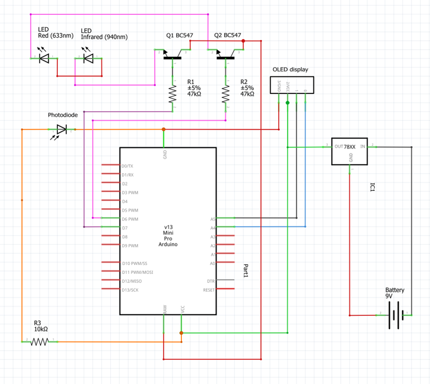
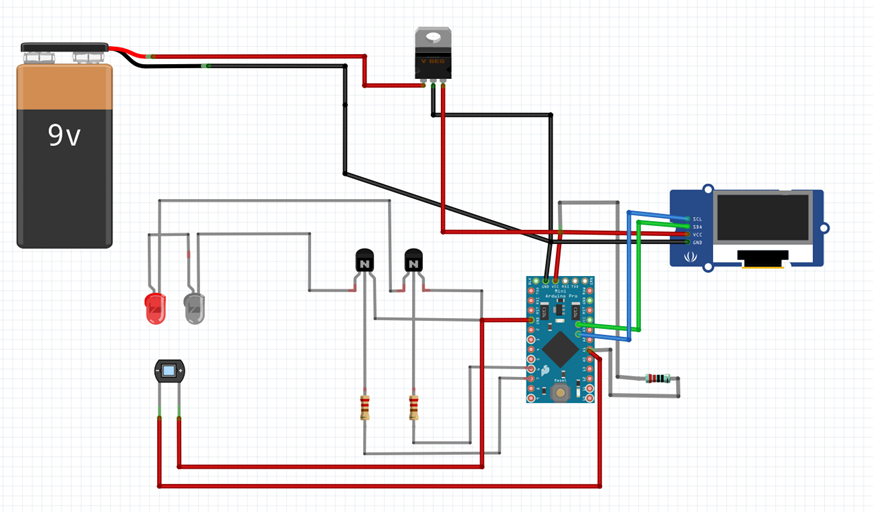
Diagram of the components
Code
Include Libraries
1#include <Wire.h>2#include <LiquidCrystal_I2C.h>This code includes two libraries:
Wirefor I2C communication andLiquidCrystal_I2Cfor controlling a 2x16 character LCD display.Define Constants
1#define maxperiod_siz 80 // number of samples in a period2#define measures 10 // periods stored3#define samp_siz 4 // samples for average4#define rise_threshold 3 // rising measures to determine a peakThese are constant values used for configuring the program. They determine the number of samples, periods, and thresholds used for calculations.
Initialize LCD Display
1LiquidCrystal_I2C lcd(0x3F, 16, 2);This initializes the LCD display with the I2C address
0x3Fand specifies the display size as 16x2.Define Pin Configuration
1int T = 20;2int sensorPin = A1;3int REDLed = 3;4int IRLed = 4;These variables define various pins used in the circuit.
sensorPinis connected to a sensor, andREDLedandIRLedcontrol LEDs emitting red and infrared light, respectively.Define Custom LCD Characters
1byte sym[3][8] = { ... };This defines three custom characters for the LCD display. These characters are later used to display special symbols on the LCD.
Setup Function
1void setup() { ... }This function runs once when the Arduino is powered up or reset. It initializes serial communication, sets pin modes, initializes the LCD, and creates custom characters for the display.
Main Loop
1void loop() { ... }This is the main loop of the program that runs continuously. It contains the core logic for reading sensor data, calculating heart rate and SpO2 levels, and displaying the results on the LCD.
Now, let's break down the main loop into several key sections:
Sensor Data Acquisition- The loop begins by reading sensor data from both the infrared and red sensors. It calculates an average value for each sensor over a short period of time.
Finger Status Check- It checks if a finger is placed on the sensor. If there's no finger detected, it displays "No finger?" on the LCD.
Peak Detection- It looks for peaks in the sensor data to detect heartbeats. When a rising peak is detected, it calculates heart rate (BPM) and SpO2 levels based on the ratio of red and infrared sensor values. It also averages these values over a short time frame.
Displaying Results- The program then displays heart rate, SpO2, and the quality of the signal (R) on the LCD. If a valid signal is detected (based on
c), it calculates and displays the BPM and SpO2 levels. Otherwise, it displays placeholders.Plotting and Array Handling- Sensor data and calculated values are sent to the serial monitor for debugging purposes. Arrays are also managed to store historical data.
Loop Continues- The loop continues to run indefinitely, repeating the above steps.
Details of the Components
Resistors — 10K and 4.7K
There are two types of resistors used in the pulse oximeter. One is a 10kilo ohm resistor, and the other is a 4.7kilo ohm resistor. Either way, a resistor is usually employed in dropping a voltage or producing a potential divider action. It might also be used to limit current flow.
Photodiode
A photodiode is a p — n junction that consumes light energy to generate an electric current. When we consider the working principle of a photodiode, a photodiode is subjected to photons in the form of light, which affects the generation of electron-hole pairs. As a result of the increase in the number of electrons on the n—side and holes on the p-side, a rise in the electromotive forces are observed.
IR LED
An infrared light-emitting diode (LED) is used for non-visual applications and nighttime illumination. The application of an infrared LED depends on its wavelength, with the common usage being between 808nm and 940nm.
Red LED
The pulse rate is measured by using the wavelength of the IR LED and the red LED light. The body scatters and absorbs visible and near-infrared wavelengths to have a measurable signal. The average number of oxygen atoms attached to a hemoglobin molecule will be observed according to the wavelength.
BC 547 transistor
BC547 is a general-purpose BJT NPN transistor with an output current of 100mA. It is ideal to use in amplifications and as a switch due to its DC gain and saturation voltage of 90mV. Especially this transistor is used in applications like sensor circuits, amplifier circuits, and many other electronic projects.
LM 7805
The LM7805 is a voltage regulator that outputs +5 volts. This voltage regulator can deliver up to 1.5A of current with current limiting and thermal shutdown features.
Battery
The purpose of the battery in this circuit is to supply voltage for the operation of the circuit. Here we use a 9V battery to give a relatively wide operating voltage range during its life without being overly high voltage.
OLED display
It provides fast oxygen saturation readings and pulse measurements and displays it conveniently on a large digital bright display. The advanced dual OLED display technology helps the user get a brighter & sharper vision of the information from a pulse oximeter.
Arduino pro mini
Arduino Pro Mini is a small-sized microcontroller board, and it comes with an Atmega328 microcontroller incorporated into the board. This board comes with 14 Digital I/O Pins and 8 Analog Pins. Because of the small size, there are many applications of Arduino Pro Mini.
For the reference, the following is the source code used.
1#include <Wire.h> 2#include <LiquidCrystal_I2C.h> 3